Portable Jammer - High Power, Broad Coverage
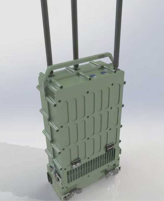
The manpack or portable jammer is a lightweight and easy to carry jammer. The jamming technology is reactive, active or hybrid. The output power (max. 250W) is exceptional high for portable jammers in the market.
The basic configuration has an output power of 250W (HF/VHF/UHF 100W, 2G, 3G, 4G, 5G, WIFI, Bluetooth 100W, 3GHz–6GHz 50W).
The following bands can be set flexible over the GUI:
- 2 × 300MHz bandwidth in the range of 20MHz – 530MHz
- 4 × 300MHz bandwidth in the range of 600MHz – 2700MHz
- 2 × 300MHz bandwidth in the range of 2700MHz – 6000MHz
The system has a total output power of 250W and could cover 20 to 6000MHz. The system can optionally be used with external antennas with polarization diversity in receiving and in transmitting mode, which can give an additional gain of 6 – 20dB (4 – 100 times better).
The system includes additional spectrum analyzer functionality.
It can be installed quickly on a backpack, car or fixed position. From that position, a 200m – 500m fiber optic cable can be deployed to control the system remotely if necessary, to stay safe from threats.
2 Antennas
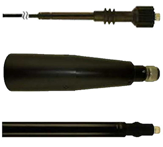
The antennas are optimized for the dedicated ranges. In the original configuration are 3 antennas included.
Antenna 1: Omnidirectional 25–512 MHz, length of 1510 mm.
Antenna 2: Omnidirectional 790–2700 MHz, gain of 4 dBi, length of 535 mm.
Antenna 3: Omnidirectional, length of 180 mm.
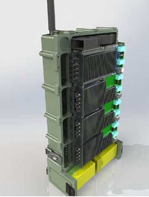
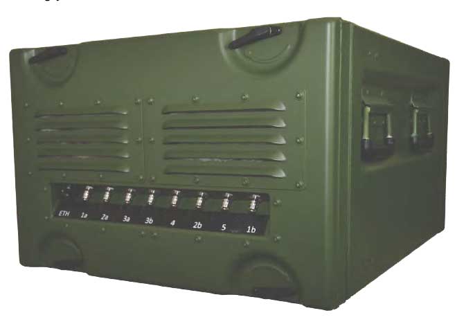
3 Housing
The Jammer housing has the following dimensions (including lids):
| Dimension | Outside (without lids) |
|---|---|
| Height: | 580mm |
| Width: | 320mm |
| Depth: | 146mm |
| Weight | 23 kg without antennas and batteries |
| Standards | MIL-STD-810 |
| Colour | Green (RAL6031-f9) |
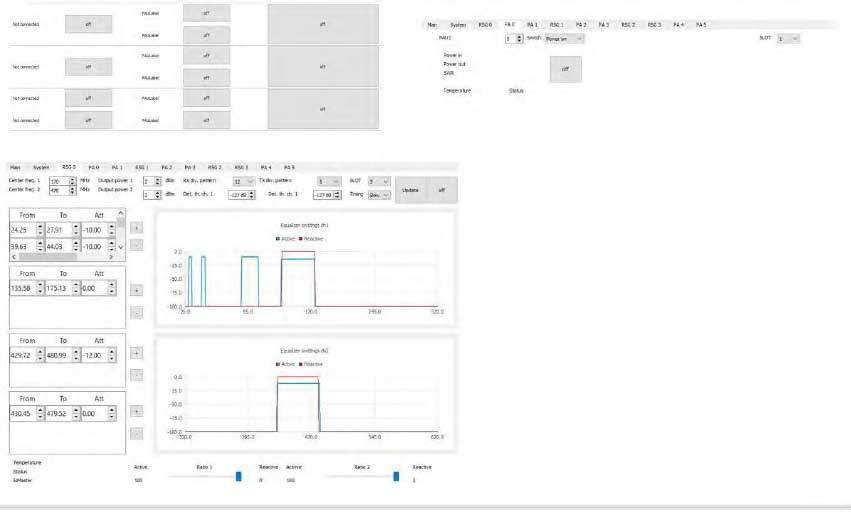
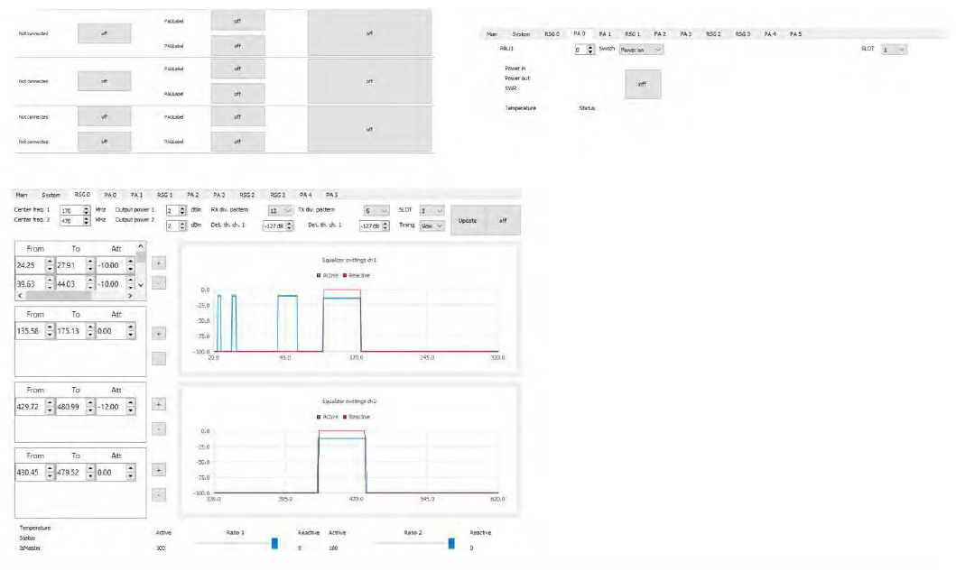
4 GUI (graphical interface)
The portable or manpack jammer can be programmed by any computer over Ethernet cable and a dedicated GUI Software.
In the GUI the operator can program the frequencies, the power and the jamming application as barrage, discrete signals and reactive. The operator can program notch frequencies (gaps) which should not be jammed. The GUI can be designed / customized on special request as per user needs. However, a standard GUI is provided.
The Jammer offers a variety of indications and alarms. All units are permanently monitored. In case a warning or failure occurs, the operator will be informed through audible tone and on the screen.
Picture as an example:
1 Main Features
The Jammer operates as a blocker to avoid wireless communication and connection. Every band can be activated independently. The system is fully reactive, active or hybrid, therefore offers excellent performance and efficiency. The system is adjustable in the frequency range between 20MHz – 6000MHz (optional > 6000MHz).
The system contains independent RF power amplifiers modules with scalable RF power, followers (signal generator) modules containing 2 bands with a bandwidth of 300MHz each. The 300MHz bands can be shifted in the RF spectrum depending on the customer needs (in the range 20MHz – 6GHz). All adjustments and control figures are done over a GUI.
Trough all the mentioned facts, the system is adjustable in size, frequencies and power output accordingly the customer needs.
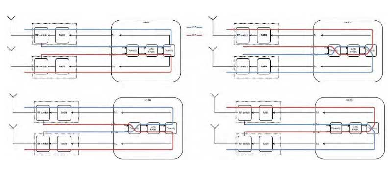
1.1 Antenna Diversity
Each follower module has two switches, and the PA has one RX and TX switch. Using this function an antenna diversity for Rx and Tx can be programmed. Four modes can be implemented and programmed. Picture below shows the possible modes.
1.2 Jamming Algorithms
-
Continuous jamming – jammer generates signal in user programmable ranges. Input RF signal has no influence on output. This mode includes algorithms as:
- Barrage permanent – device is generating noise signal on defined frequencies with defined power.
- Custom permanent – device uses previously saved signal, bandwidth and numbers of carriers can be adjusted and uploaded from a preloaded file.
- Waveforms can be generated accordingly customer needs.
-
Reactive jamming – jammer reacts on RF input signal by generating/replaying signal on output with predefined power. This mode includes algorithms as:
- Reactive – generating output signal when input power is above a defined threshold.
- Reactive – generating an output signal according to input signal.
- Reactive – generating an output signal according to input signal, if there is no signal detected in the programmed band, the signal generator create in the whole band a white noise with maximum power.
Both active and reactive jamming can be combined in the same band (hybrid)
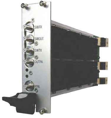
3 Power Amplifier Modules
There are three types of PA, low frequencies from 20 MHz to 700 MHz, middle frequencies from 700 MHz to 2700 MHz and for high frequencies 2700MHz – 6000MHz (optional up to 40GHz). It amplifies the input signal up to 50dBm (100W) to the output port.
A RF switch is integrated in the PA. This allows to use the same antenna as a receiving and transmitting antenna.
The PA can be set to have the amplification permanently on or off, or to switch in auto mode. In auto mode, the PA is switched on/off according to the timing. In addition, the operator can define the output power between 8dBm to 50dBm.
The RF-switch setting is made via the PA itself. There are 4 different states. There is the RX mode, which routes the antenna input to the RX port. TX mode, which routes the antenna input to the TX port. And there is the switch mode, which switches the antenna input to TX or RX according to timing.
| Type | From | To | Power |
|---|---|---|---|
| PAL | 20 MHz | 620 MHz | 100W |
| PAM | 620 MHz | 2700 MHz | 100W |
| PAH | 2700 MHz | 6000 MHz | 100W |
- Module dimensions PAL/PAM: (L × W × H): 245 × 130 × 40 mm
- LPA and MPA weight: 2240g
- Module dimensions PAH: (L × W × H): 245 × 130 × 80 mm
- HPA weight: 4500g
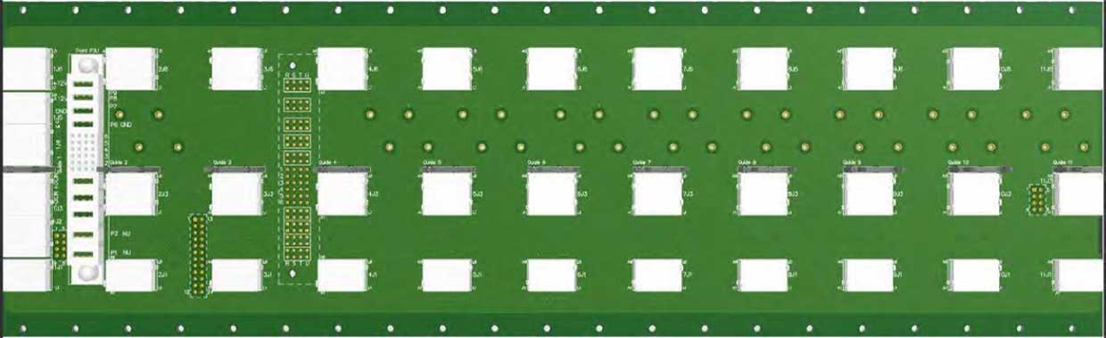
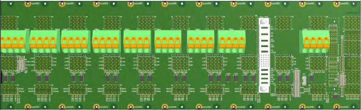
4 Backplane
The backplane connects all modules together for communication, power supply and synchronization.
- Dimensions (L × W × H): 430 × 130 × 42 mm
- Weight: 750g
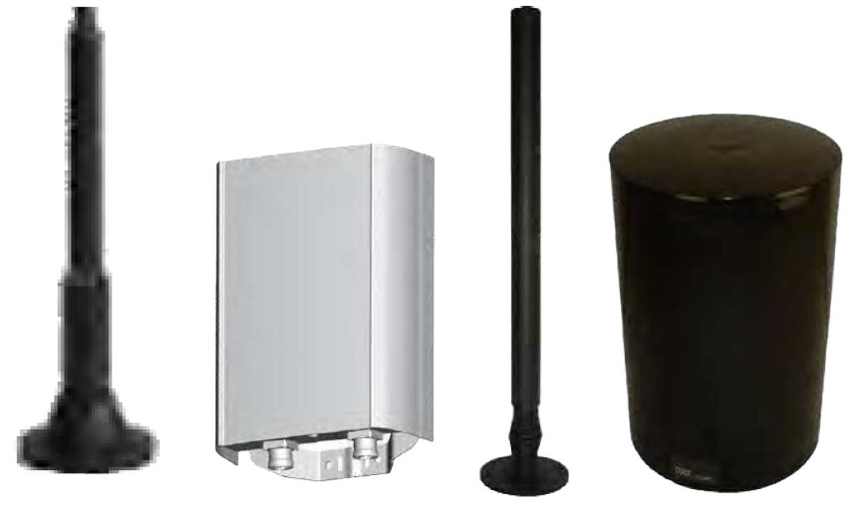
5 Antennas
The antennas are optimized for the dedicated ranges. All antennas are 50 Ohm. For the application as convoy jammer, two omni antennas are in the range of 20 MHz – 620 MHz, a 800–2690 MHz X-Pol Panel Antenna, two omni antennas in the range of 900 MHz – 2700 MHz, and a 200–6000 MHz omni antenna are used.
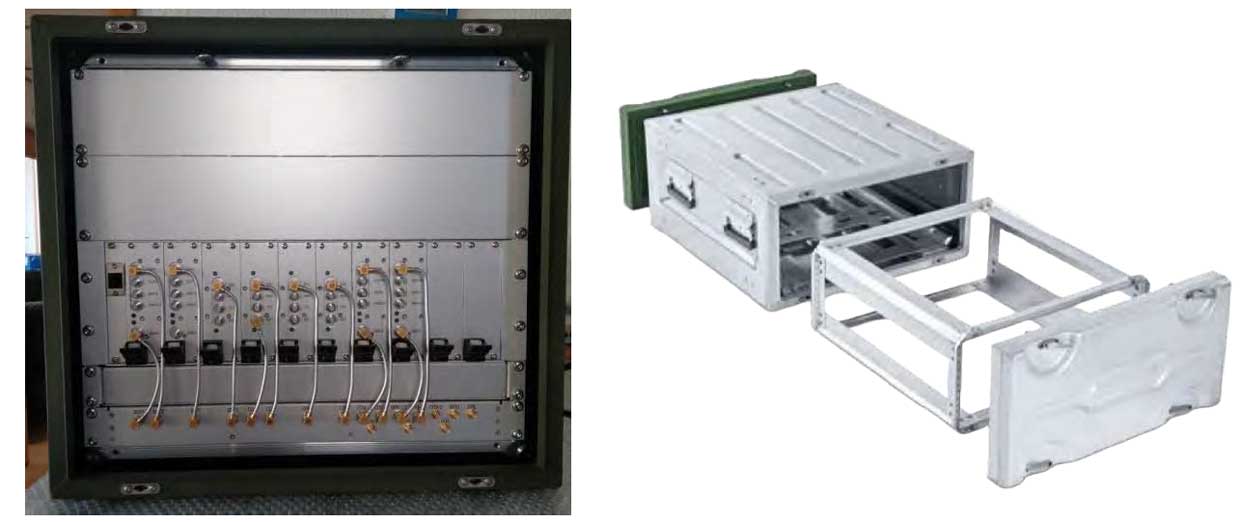
6 Housing
The dimensions of the Jammer housing are according to the final design in frequencies and power. The following pictures are examples:
7 GUI (graphical interface)
With the GUI the operator can program the frequencies, the power and the jamming application as barrage, discrete signals and reactive. The operator can also program notch frequencies (gaps) which should not be jammed. The GUI can be designed / customized on special request as per user needs. However, a standard GUI is provided.
The Jammer offers a variety of indications and alarms. All units are permanently monitored. In case a warning or failure occurs, the operator will be informed through a tone and/or on the screen.
8 Operational Power Source
The system uses 9V – 36V, backed by a battery this guarantees independent power from an alternator or the grid according to the capacity of the battery. The system is directly connected to the battery and the battery is directly connected to the charger, which is either on AC (grid anywhere in the world) or additional alternator.
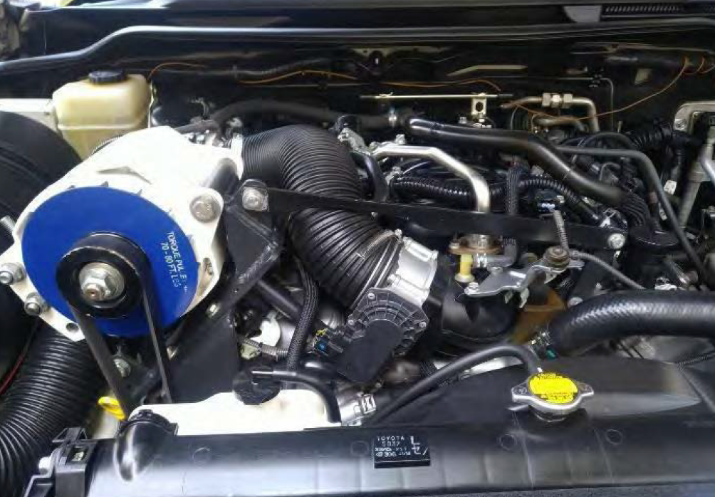
10.1 Car example
Toyota Landcruiser

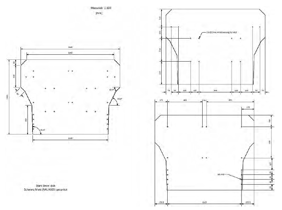
10.2 Mounting Plate
The mounting plate will be attached at the car cassis and the system will be attached to the mounting plate.